Figure 4. This photo shows the bottom of the right bolt head locking lug protruding below the bottom edge of the extractor claw. Note that the bolt is upside-down so the underside of the bolt is at the top of the picture.
In the first condition the bolt head is essentially not properly "timed" to the bolt body and extractor. That is, with the bolt head in the extended position, the bolt head locking lugs are rotated a few degrees out of the plane of the bolt guide ribs and the extractor. This is typically seen most easily by looking at the extractor claw with the bolt head in the extended position. The upper face of the right locking lug will be recessed below the top edge of the extractor claw and the lower face of the right lug will protrude below the bottom edge of the extractor claw. A poor matching of bolt head and extractor are the most likely causes. One possible solution is to try alternate combinations of bolt heads and extractors to find a pair that matches well for a particular bolt body.
The other condition appears at first to be very similar to the first case however it has a different cause. In the second condition the bolt head locking lugs are wider than the bolt guide ribs and/or the extractor claw. This is evident if one measured the guide ribs, extractor claw, and locking lugs with a caliper. Also, this condition will be visually apparent when looking at the alignment of the locking lugs and the extractor with the bolt head extended. Unlike the first condition, the upper face of the right locking lug will typically be flush with the upper surface of the extractor claw while the lower face of the right locking lug will protrude below the lower surface of the extractor claw.
In both cases the top of the left lug is typically too high and the bottom of the right lug is too low (protrudes below the extractor). For both conditions the preferred solution is to replace the bolt head and/or the extractor. An alternative albeit less desirable solution is to remove some metal from the lugs.
When the bolt is in battery (i.e., bolt fully closed and locked), the rear surfaces of the bolt head locking lugs bear against the locking recesses in the receiver. The upper and lower surfaces of the locking lugs do not contribute directly to this locking action. Therefore, I believe it to be of no harm to remove a small amount of metal from the top or bottom surfaces of the bolt head locking lugs. DO NOT remove any material from the rear of the locking lugs as this will increase headspace. The idea is to make the top and bottom surfaces of the locking lugs flush with the extractor and guide ribs.
Figure 4. This photo shows the bottom of the right bolt head locking lug protruding below the bottom edge of the extractor claw. Note that the bolt is upside-down so the underside of the bolt is at the top of the picture.

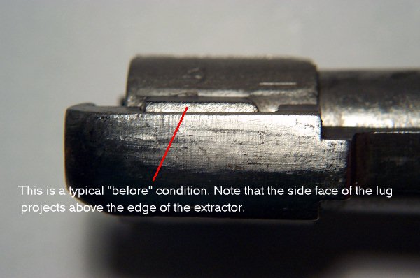
Figure 5. The red line in this photo shows the surface on the top of the bolt body guide rib that should align with the top surfaces of the extractor and the bolt head locking lug.

Figure 6. This photo shows the bolt head in the extended position.

Figure 7. This is an "after" photo showing a bolt head on which the bottom surface of the right locking lug has been cut with a file to eliminate protrusion below the extractor.